

Wall
Профили для стен и потолков
Выполняют декоративную функцию и компенсируют деформации возникающие в швах
Standart
Стандартные профили
Для деформационных швов в полах, используются в местах с низкой и средней интенсивностью движения
Heavy
Тяжелые профили для полов
Для полов с высоким трафиком движения
Hydro
Водонепроницаемые профили
Водонепроницаемые профили для зданий и сооружений
Metall
Стальные профили
Для больших нагрузок с высокой несущей способностью
Control
Dewmark Flex
cords
шнуры
Бентонитовые шнуры Дьюмарк Бент
Шнуры на основе природного бентонита натрия служат для гидроизоляции заглубленных сооружений
резина
Шнуры из гидрофильной резины Дьюмарк Ватерфил
Созданные на основе EPDM и гидрофильного полимера, набухающие при контакте с водой, шнуры создают активные барьеры против воды под давлением
Защитные и антивандальные уголки призваны защитить углы колонн и стен от механических воздействий. В зависимости от материала из которого они выполнены могут обладать ярким демпфирующим эффектом.
Используя различные материалы исполнения вкупе с широкой цветовой гаммой мы можем произвести и подобрать уголок под любой интерьер.
Напольные плинтусы призваны обеспечить переход от пола к стене без образования щелей и канавок. Мы производим несколько типов плинтусов:
- Алюминиевые прямые - декоративные плинтусы
- Промышленные алюминиевые плинтусы с кабель-каналом
- Легкие промышленные гибкие ПВХ Плинтусы
- Промышленные плинтусы из ПВХ для помещений с агрессивными средами
Dewmark Concrete SG 63

- Downloads
- Calculator
- Description
- Technical data
-
LoadsLoads (EN)  330.80 kB
DrawingsSend a request to baltic@dewmark-joint.com
Certificates1853-CPR-108 Dewmark steel EN 1.24 MB
-
Calculation of base plates and loads
 CalculateSelection result
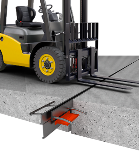 Application of support plates. Load bearing calculations.
The use of base plates was the development of the evolution of Omega profiles for concreting work joints. Due to the quick-detachable casing, adjacent to the body of the base plate, and an increase in the area of contact between the base plate and concrete, it was possible to increase the load-bearing loads of the floor.
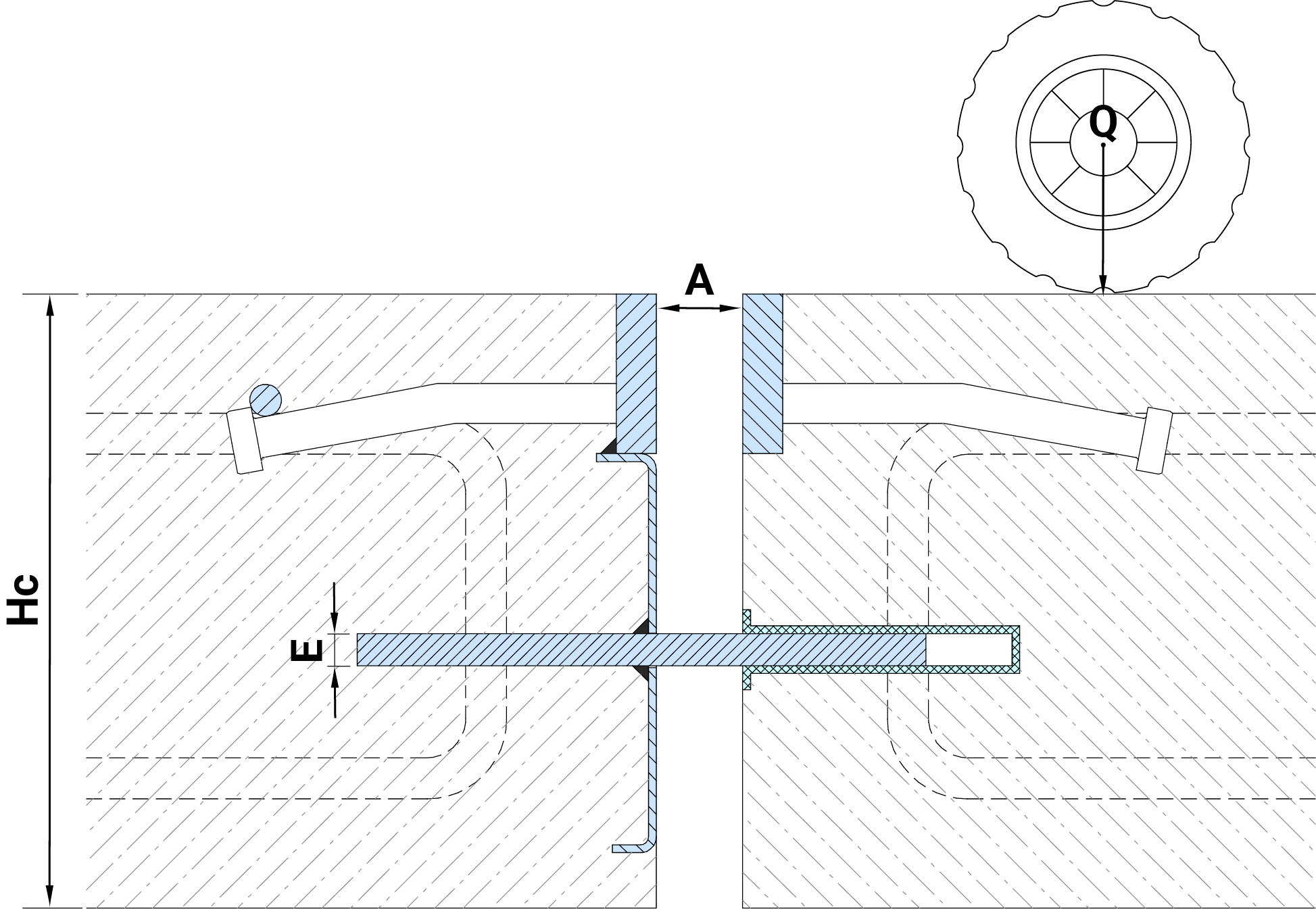
The support plates carry and transfer the load between two adjacent sections of the concrete floor, that is, the loaded equipment moves along the finished floor without causing stress in the concrete slab. A concrete slab usually has only about 50% of its bearing capacity at the edges, so the dowels support the slab at the edges and help to support and transfer weight from one slab to another, allowing the slabs to bend slightly, gently transferring the load along its surface.
Calculation of the bearing capacity of the base plates is given in the British methodological manual TR34 ver. 4 clause 6.5.
The force on the shear of the base plate is determined by the formula:
Where - cross-sectional area of the base plate
- steel yield strength
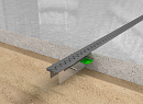
Bearing / bending load on the base plate:
Where
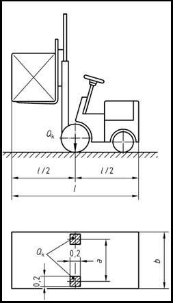
- distance of load application from the concrete surface; with a symmetrical arrangement, this is equivalent to half the seam opening (see fig.)
(constant)
= concrete strength =
- base plate width
- base plate thickness
- the strength of the steel of the base plate (taken equal to the yield strength of the steel)
Loader category by sizeCategory , m , m , m G1 0,85 1,00 2,60 G2 0,95 1,10 3,00 G3 1,00 1,20 3,30 G4 1,20 1,40 4,00 G5 1,50 1,90 4,60 G6 1,80 2,30 5,10
Loader category Weight Limit, kN Lifting capacity, kN Axle load*, kN Wheel load*, kN Distributed load per m2, (kN/м2) Wheel-to-surface contact area, mm mm Loader G1 31 10 26 12,5 12,5 200х200 Loader G2 46 15 40 15 15 200х200 Loader G3 69 25 63 31,5 17,5 200х200 Loader G4 100 40 90 45 20 200х200 Loader G5 150 60 140 70 20 200х200 Loader G6 190 80 170 85 20 200х200 * - shock-free
-
Description
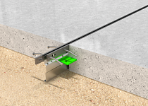
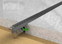
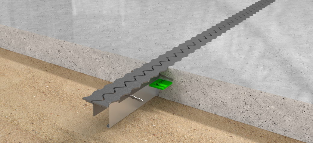
Profile for concrete joints with flat sinus top plates. Due to its geometry, it allows impact-free passage through the expansion gap, even with steel wheels, in-creasing the performance of the concrete floor while reducing vibration and noise during the expansion gap.
The profiles are designed for loads according to TR 34 4th edition and Eurocode 2: EN 1992-1-1.
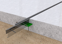
Together with the load transfer system, it allows two adjacent slabs to be in one plane even with a gap open-ing of 20 mm.
Produced with two types of top plates to choose from: straight side edges (type SG 63) and corrugated side edg-es to increase the resistance of floors to dynamic loads (type SG 63-ZZ)
It perfectly reinforces the edges of the concrete on both sides of the shrinkage joint and serves as a reliable system for transferring loads during storage and when the equipment passes through the joints.
Components (specification)1 Steel flat sinus plates (2 types)1 2 Steel guide brackets 3 Profile body 4 Load transfer dowel (3 types)2 5 Dowel steel casing 6 Riveted fasteners 7 Welded screw 8 Nut 9 Dowel mounting bracket 10 Steel rivet 11 Fixing screw 1 It is available in two types of top plates:
- SG 63 - with straight side edges;
- SG 63-ZZ - with wavy sides.

-

Profile Hp (mm) Hc (mm) A (mm) B (mm) С (mm) D (mm) E1 (mm)
u/c2 (mm)
c/c3 (mm)
L(mm) SG 63/90-...1 90 100-120 80 220 5 55 5 / 8 / 8XL 220 600 / 500 3000 SG 63/110-...1 110 125-140 80 220 5 60 5 / 8 / 8XL 220 600 / 500 3000 SG 63/130-...1 130 145-160 80 220 5 70 5 / 8 / 8XL 220 600 / 500 3000 SG 63/150-...1 150 165-180 80 220 5 80 5 / 8 / 8XL 220 600 / 500 3000 SG 63/180-...1 180 185-210 80 240 5 100 5 / 8 / 8XL 220 600 / 500 3000 SG 63/210-...1 210 215-240 80 260 5 110 5 / 8 / 8XL 220 600 / 500 3000 SG 63/240-...1 240 245-270 80 260 5 125 5 / 8 / 8XL 220 600 / 500 3000 SG 63/270-...1 270 275-300 80 260 5 140 5 / 8 / 8XL 220 600 / 500 3000 1... — Dowel thickness and type. Selected depending on the loads (see Calculation of loads).
2c/c — Distance between dowel centers (600 mm for 60/OP-5 and 60/OP8, 500 mm for 60/OP8XL— see Calculation of loads).
3c/c — Profiles can be produced to any height on request.PARTS MATERIALS AND MANUFACTURING METHODS (as per specification)Profile № Component Steel EN Manufacturing method 
1 Steel sinus strip (5 mm) S235J0 10051 Laser cutting + hot-dip galvanized HDG* S235J0 10051 + galvanized according EN 1461 + steel strips AISI 304* 1.4016 10088-2 Laser cutting 2 Steel angle S235J0 13918:2017 Stamping, bending 3 Profile body DC01 10130:2006 Stamping, bending 4 Dowel S355J0 10025-2 Laser cutting + hot-dip galvanized HDG* S355J0 10025-2 + galvanized according EN 1461 + steel strips AISI 304* 1.4016 10088-2 Laser cutting 5 Dowel casing DC01 10130:2006 Stamping, bending * — On request, the profiles can be fully or partially produced from corrosion-resistant steels: hot-dip galvanized (HDG) structural steels or stainless (AISI 304) steels. In this case, special designations are added to the profiles: For HDGHDG — the upper strips are galvanized;
HHDG — the upper strips with anchors + dowels are galvanized;
FHDG — the profile is fully galvanized.
For AISI 304SS — upper strips made of AISI 304 steel;
HSS — upper strips + dowels made of AISI 304 steel;
FSS — profile made entirely of AISI 304 steel.
MANUFACTURING TOLERANCESLength: ±0,1 mm Height: ±1 mm Straightness: ±0,5 mm/m Curl: <0,50/m